
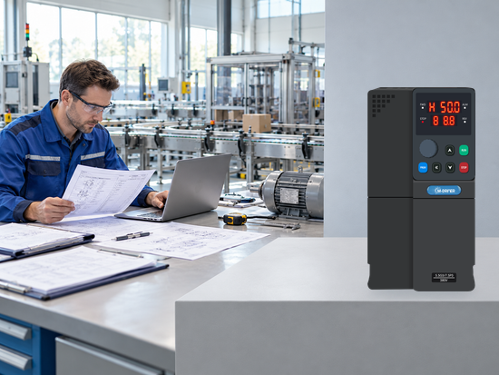
Before ordering a replacement drive, confirm what the existing machine needs to keep doing. The useful questions are practical: will it fit, will the controls work as intended, which accessories need review, and how will the completed change be accepted? A matching power label does not answer those questions.
The starting point for a VFD replacement is a clear compatibility record, not a copied parameter list or an assumed equivalent model. This guide sets out the information to collect and the decisions to resolve with qualified personnel. It is a procurement and project-planning checklist, not a universal installation or parameter-setting procedure.
1. Describe the machine before selecting the replacement
Begin with clear photographs of the motor and existing drive nameplates, the supply details and a short process description. Add available operating records: current under normal and demanding conditions, speed range, start and stop frequency, direction changes and required stopping behavior. Label measured values with the load condition and data source; leave unavailable details marked for review rather than filling them with estimates.
Then describe the functions that operators depend on. Does a selector switch choose local or remote control? Does the PLC set speed, select preset values or only issue a run request? What should happen after a communication interruption, power restoration or process interlock? A drive that turns the motor correctly can still be incompatible with the machine sequence.
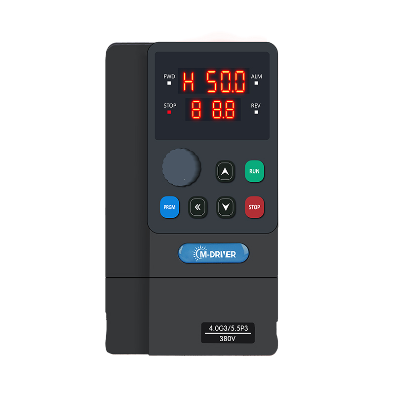
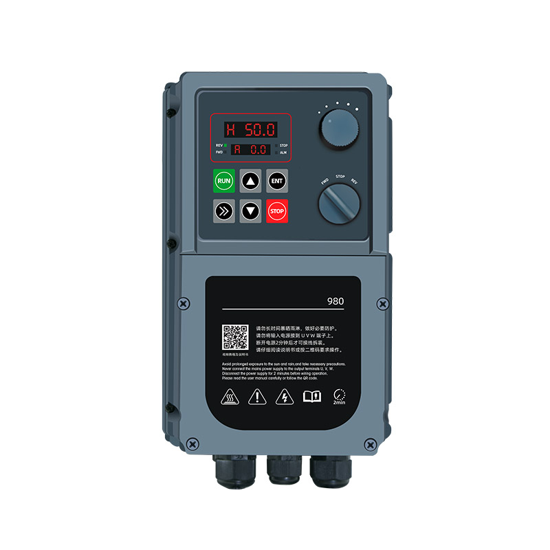
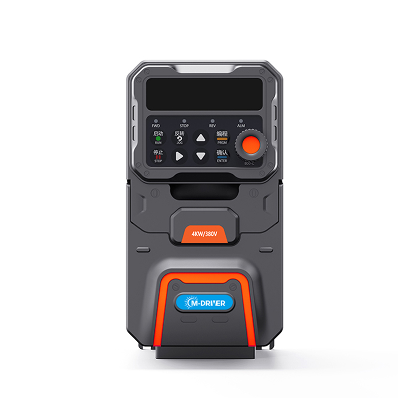
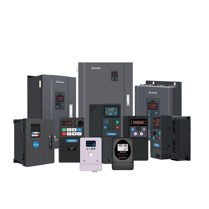
When reviewing M-Driver industrial AC drives, include the M-Driver 900 Series Variable Frequency Drive (VFD) as a candidate only after the application requirements are defined. It provides V/F and sensorless vector control options. That is a starting point for assessment, not evidence that any existing drive, interface or machine function can be replaced without modification.
2. Separate electrical fit from mechanical fit
Electrical compatibility includes the supply arrangement, voltage class, motor type, continuous output current and the required overload duty. Check these at the actual ambient temperature, altitude and installation conditions. A catalog rating and the usable rating inside a hot enclosure may not be the same.
For a VFD retrofit, mechanical compatibility is a separate check. Compare overall dimensions, mounting pattern, cable-entry access, bend space, ventilation paths and service access. Leave room to operate isolators and remove covers safely. A smaller enclosure does not automatically make a replacement easier if the terminals or cooling paths become inaccessible.
Document both checks before ordering. If a new mounting plate or enclosure alteration is needed, include it in the work scope. Do not present an improvised fit as a drop-in replacement. Any changes to the electrical installation must be designed and completed by qualified personnel under the site's isolation and verification procedures.
3. Translate functions, not terminal numbers
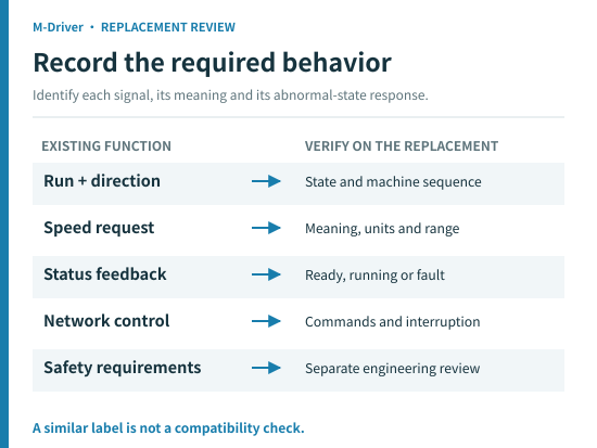
To review drive compatibility, create one row for every active interface. Write down its purpose, electrical characteristics, normal state, abnormal state and intended destination. Terminal names that look similar can have different voltage levels, reference arrangements or logic.
Existing function | Evidence to collect | Acceptance question |
Run and direction requests | Circuit drawing, contact type, sequence | Does the new logic preserve the intended operation? |
Speed reference | Signal type, range, scaling, source | Does the same request produce the required process speed? |
Ready and fault outputs | Relay or electronic output, load, polarity | Will the PLC interpret every state correctly? |
Network commands | Protocol, data map, units, timeout action | Are commands and feedback mapped and tested? |
Stop and safety functions | Risk assessment, independent circuits | Is the required safety architecture maintained? |
A PLC speed command must be interpreted in its configured units and scaling. The same transmitted value can have different meanings on different platforms; copying it without checking the definition may produce the wrong operating request. Likewise, an output labeled “ready” must be checked against the PLC's actual expectation, not treated as interchangeable with “running.”
Treat safety-related functions as a firm engineering boundary. An ordinary run input or fault relay is not a substitute for a required certified safety function. If the replacement changes the safety architecture, obtain an appropriate assessment before proceeding. Do not infer a safety capability from the presence of a stop button.
4. Decide what can be reused—and what needs redesign
Existing accessories deserve their own review. A braking resistor, filter, reactor, external keypad or communication accessory should not be transferred merely because it is already installed. Compatibility depends on the replacement drive's supported arrangement and the application's duty.
Use three decisions: retain after verification, replace with a compatible item, or stop pending engineering review. Put the evidence and responsible person beside each decision. This keeps an unconfirmed accessory out of an otherwise attractive quotation.
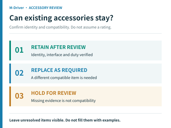
For an existing braking resistor, for instance, collect identification, resistance, power rating and operating duty, then obtain compatibility confirmation for the candidate drive. Do not select it by physical size or assume the old stopping performance will remain unchanged. The same principle applies to an external operator panel: a similar connector is not proof of compatibility.
Include a review of the motor and cable condition in the project scope where needed. Leave electrical testing to qualified personnel using procedures appropriate to the equipment and site. Establish the methods and conditions for this installation instead of copying test values or terminal arrangements from an unrelated job.
5. Rebuild settings from an approved requirements sheet
A parameter backup is valuable evidence, not a universal configuration file. Preserve the old settings and software versions where possible, but translate their meaning into the replacement's functions. Parameter numbers, units, defaults and interactions can differ between platforms.
Organize the required behavior by purpose: motor data, control method, command source, speed reference, limits, ramps, protection, outputs and communication behavior. Mark each item as confirmed, requiring engineering review, or requiring acceptance testing. Do not insert a generic setting simply to complete the sheet. Record why a non-default function is needed so a later technician can understand the machine, not just repeat a number.
Pay particular attention to restart behavior. Reapplying power, restoring a network or resetting a fault must not unexpectedly restart hazardous machinery. Verify the complete control sequence, including commands that remain present while the drive is unavailable. A successful local keypad test does not validate remote operation.
6. Plan acceptance tests and a rollback decision
Agree on the acceptance criteria before the shutdown. Qualified personnel should establish an authorized test plan covering the relevant controls and representative process operation. Direction, actual speed, current, stopping behavior, interlocks, PLC feedback and required abnormal-state responses should have clear acceptance criteria. Record any untested functions or operating conditions before the machine is handed over.
Use the same reference conditions when comparing old and new results. A current reading taken with an empty machine cannot demonstrate performance at production load. Record both the test conditions and the result, including any limits that were not tested.
Define a rollback decision point and the resources required. Where reverting is technically possible, preserve the original configuration, labeled connections and recoverable installation arrangement. Where the old drive has failed or rollback is impractical, plan another recovery route. Do not promise that restoring the old unit will always be available.
Close the project with revised drawings, approved settings, software backups and an operator handover. A VFD replacement is complete when the machine's agreed functions have been demonstrated—not when the new drive first shows a running frequency.
FAQ
Can I replace a drive with another one of the same kW?
Power is only one screening item. Supply, motor compatibility, output current, duty, interfaces, accessories and safety requirements must also match. Check the complete application before purchasing.
Can I copy the old drive's parameter numbers?
No. Transfer the required function and engineering value, then configure the corresponding function on the new platform. Preserve the old backup for reference rather than treating it as a universal import file.
Can existing PLC programs and accessories remain?
Possibly, but retention requires verification. Review signal levels, scaling, command mapping, feedback and fault responses. Confirm accessory compatibility separately and identify any PLC changes in the quotation scope.
What should I send for a replacement review?
Send both nameplates, the existing wiring diagram, settings backup, operating duty, interface list, accessory details and clear installation photographs. Identify the shutdown window and any functions that must remain unchanged.
Prepare a reviewable replacement request
For your next VFD replacement, send M-Driver the machine requirements and existing installation record before choosing a model. Contact M-Driver with the compatibility sheet, the items still unresolved and the planned shutdown window. The next step is to review the candidate and modification scope together, not to assume that matching one rating establishes a direct replacement.