
Selecting a variable frequency drive for a fan is not simply a matter of matching the kilowatt number on the motor nameplate. A reliable selection must also match the motor current, supply voltage, fan load profile, required speed range, control signal, installation environment, and operating duty.
A complete fan VFD sizing process should therefore begin with measured and nameplate data, then account for the real installation conditions.
This guide explains how to choose a VFD for industrial fans without oversimplifying the engineering. It is intended for centrifugal fans, HVAC air-handling units, cooling towers, dust collection systems, ventilation equipment, and industrial blowers. If the machine uses a different fan type or has unusual starting torque, confirm the load curve before making the final selection.
Why Use a VFD for an Industrial Fan?
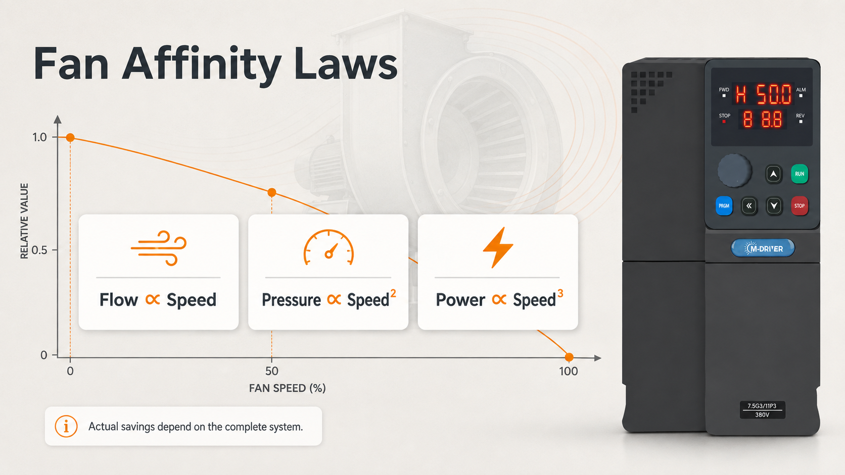
Many fan systems control airflow with dampers while the motor continues to run near full speed. A VFD changes motor speed so airflow can follow actual demand. In a centrifugal fan system, flow is approximately proportional to speed, pressure is related to the square of speed, and power is related to the cube of speed under ideal affinity-law conditions.
This relationship explains why variable-speed control can reduce energy use when the process does not require full airflow. Actual savings depend on duct losses, minimum ventilation requirements, operating hours, motor efficiency, and the control strategy. A responsible supplier should not promise one fixed saving percentage before reviewing the system.
A VFD can also provide smoother acceleration, reduce mechanical shock, support automatic pressure or airflow control, and make it easier to connect the fan to a PLC, building management system, or local control panel.
Step 1: Read the Motor Nameplate
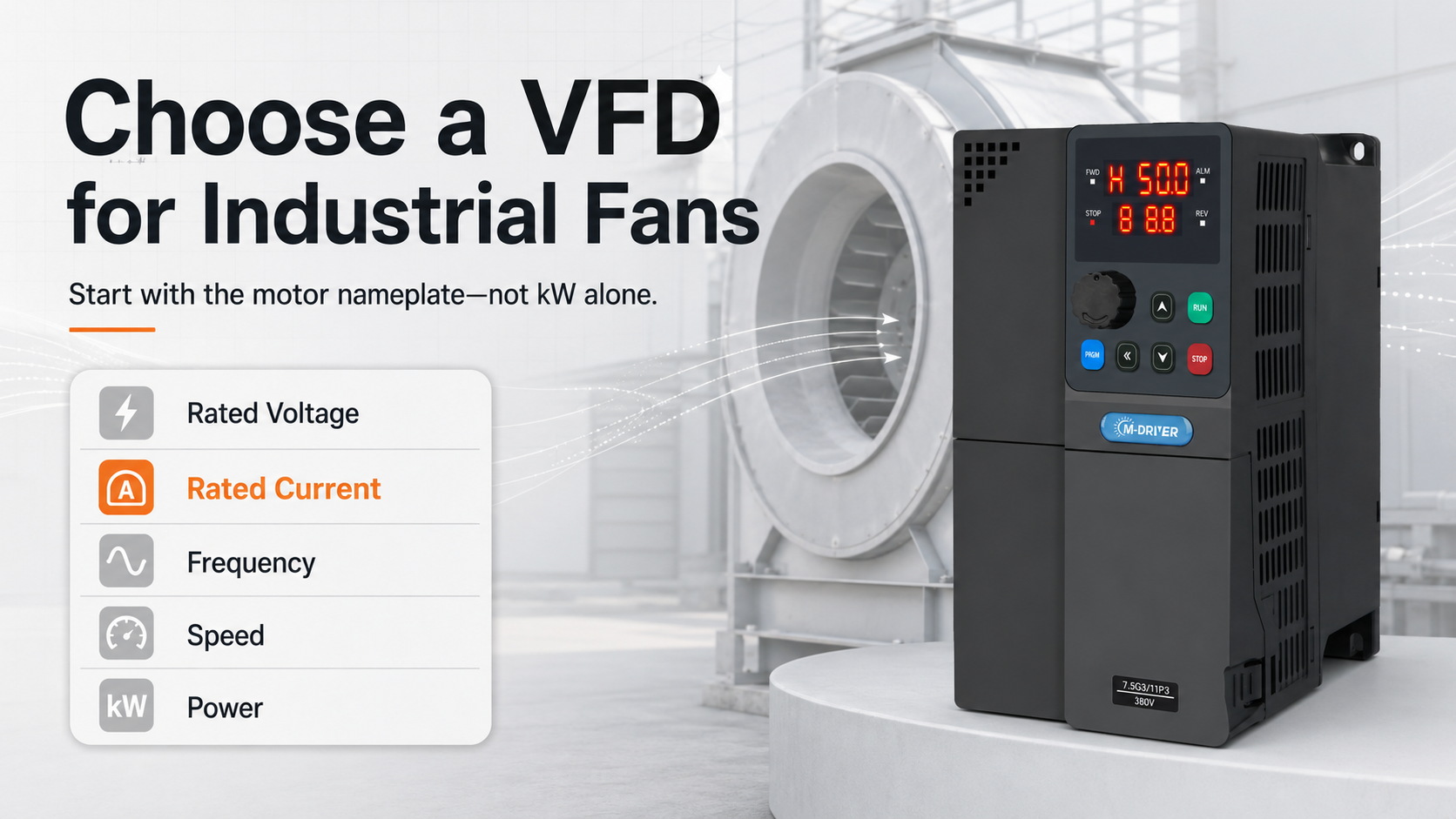
Start with the motor nameplate, not the fan catalog alone. Record:
Rated power in kW or hp
Rated voltage and phase
Rated current
Rated frequency
Rated speed
Motor type
Insulation and duty information
The most important sizing value is usually the motor rated current at the actual operating voltage. Two motors with the same power can have different rated currents. The selected VFD must be able to supply the required continuous current and any overload demanded by the application.
Do not select the drive only because its power rating matches the motor. Always compare the VFD rated output current with the motor nameplate current.
Step 2: Confirm the Available Power Supply
The VFD input voltage must match the site supply, and the VFD output must be suitable for the motor voltage. Confirm the actual supply tolerance, frequency, grounding arrangement, and whether the network is stable.
Also check whether the site experiences voltage dips, generator operation, frequent switching, or weak-grid conditions. These details can affect drive sizing, protection settings, and the need for input reactors or other accessories. Never assume that every unit in the same power range accepts the same voltage class.
Step 3: Identify the Fan Load Type
Most centrifugal fans are variable-torque loads, but not every fan application is identical. A clean HVAC supply fan may have a predictable load curve, while a dust extraction fan can experience changing filter resistance. A process blower may require higher starting torque or a restricted operating range.
Ask these questions:
Is the fan centrifugal, axial, or a positive-displacement blower?
Does it start with an open or closed damper?
Is the airflow requirement continuous or intermittent?
Can the filter or duct resistance change significantly?
Is reverse rotation prohibited?
Is there a minimum safe speed for cooling or process airflow?
If the load behaves more like a constant-torque machine, do not use a lighter fan-duty assumption without checking current and overload requirements.
Step 4: Fan VFD Sizing by Current and Overload Duty
For a standard variable-torque fan, the motor rated current is the starting point. Select a VFD whose continuous output current is at least equal to the required motor current under the real operating condition.
Then review overload duty. Fans normally need less overload capability than conveyors, crushers, or hoists, but additional torque may still be needed during acceleration, after a process upset, or when the fan starts against pressure. Oversizing by an arbitrary percentage is not a substitute for checking the drive current table and duty rating.
If several motors will be connected to one drive, the selection method changes. The combined current, individual motor protection, operating sequence, and switching method must all be reviewed. Do not switch a motor on the VFD output while the drive is running unless the complete system is designed for that operation.
Step 5: Choose the Control Method
V/F control is often suitable for straightforward fan speed regulation, especially where the load changes gradually and precise low-speed torque is not required. Sensorless vector control can provide better torque response and speed stability when the load changes quickly or the operating range is wider.
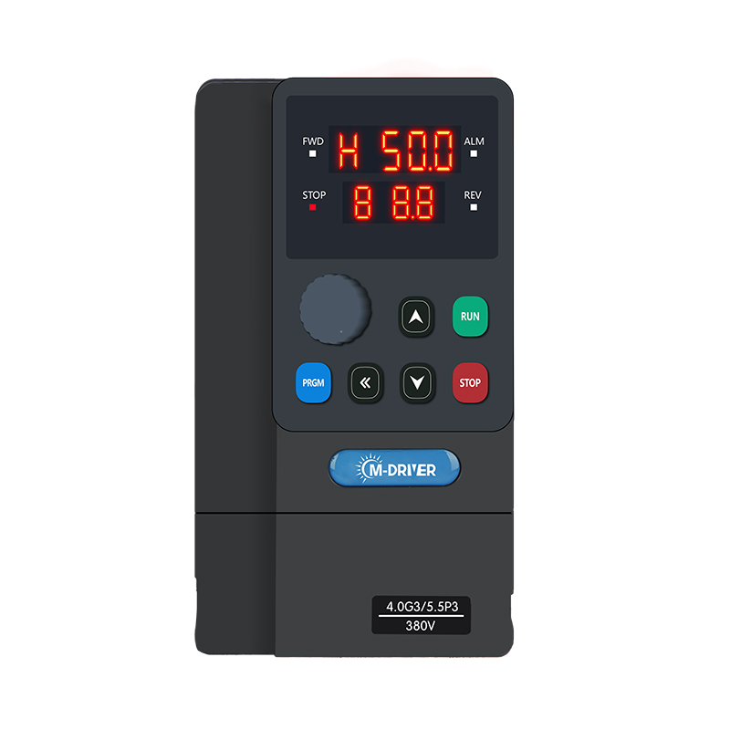
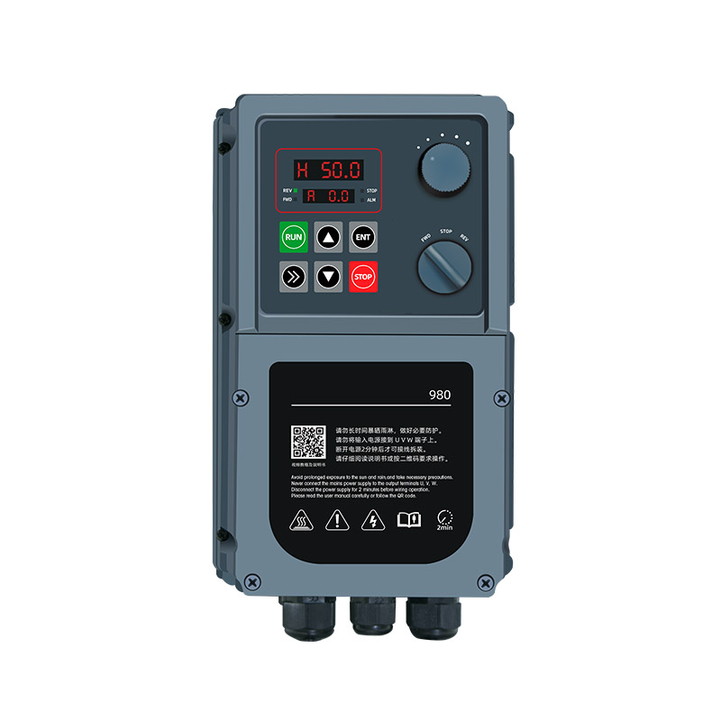
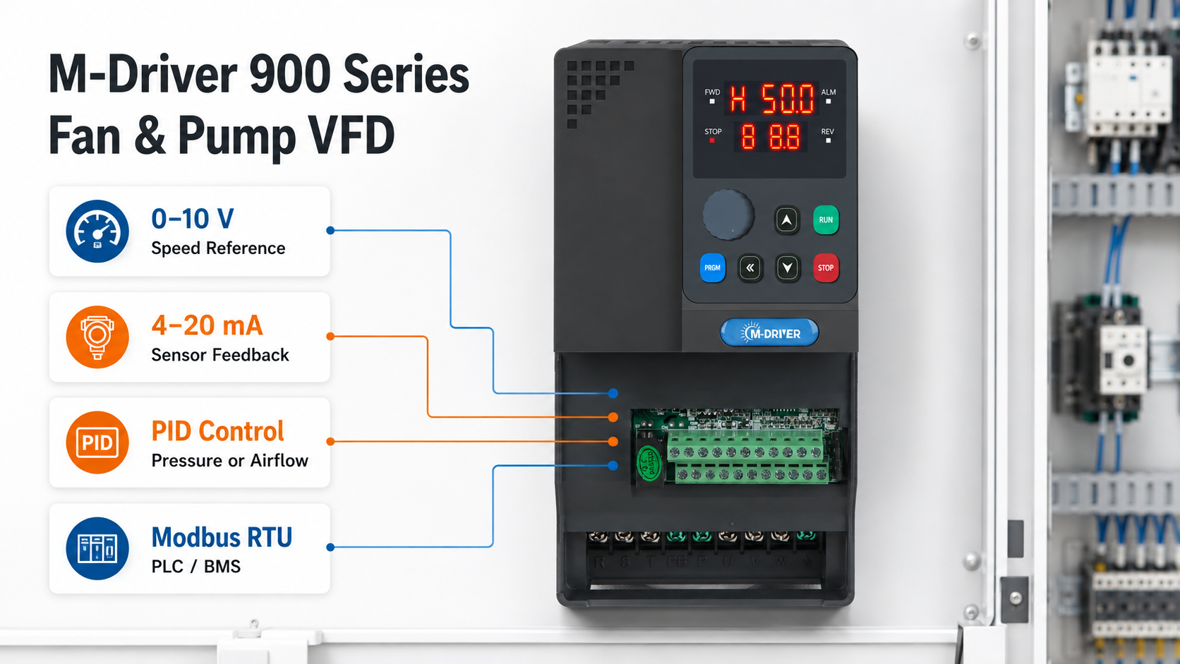
The M-Driver 900 Series Fan and Pump Variable Frequency Drive (VFD) supports both V/F control and sensorless vector control, allowing the control mode to be selected according to the motor and fan duty. It also supports panel, terminal, and communication command sources.
For closed-loop airflow or pressure control, check the feedback signal. Common transmitters use 0–10 V or 4–20 mA. The 900 Series supports analog signal input and built-in PID control, which can be used to adjust fan speed from a pressure, airflow, or process feedback signal after correct commissioning.
Step 6: Define the Speed Range
A VFD can reduce fan speed, but the minimum operating frequency should not be chosen arbitrarily. At low speed, the motor’s shaft-mounted cooling fan also slows down. The process may require minimum airflow for ventilation, cooling, combustion, or material transport.
At the upper end, do not raise the motor frequency beyond its approved mechanical speed simply because the VFD allows a higher output frequency. Confirm fan impeller limits, motor bearings, vibration, balance, noise, and the manufacturer’s maximum speed.
The final minimum and maximum frequency settings should protect both the fan and the process.
Step 7: Check the Installation Environment
Temperature, altitude, dust, moisture, corrosive gas, vibration, and cabinet ventilation affect the selection. A drive installed in a hot or high-altitude cabinet may need derating. An IP20 drive is intended for a protected indoor installation and should not be treated as a waterproof enclosure.
Also check the motor cable length. Long output cables can increase reflected-wave stress and leakage current. Depending on the voltage, cable, motor insulation, and length, an output reactor or dv/dt filter may be required. Keep power cables separated from analog and communication wiring, and use grounding and shielding practices appropriate to the site.
Step 8: Specify the Control and Communication Requirements
Before requesting a quotation, define how the fan will be operated:
Local keypad start and speed setting
External start/stop terminals
0–10 V or 4–20 mA speed reference
Pressure or airflow transmitter with PID control
Multi-speed terminal control
PLC or supervisory control through Modbus
Fault relay and analog output requirements
This prevents a common purchasing problem: the VFD power rating is correct, but the available I/O does not match the control panel design.
Common Fan VFD Selection Mistakes
Selecting by kW only
The motor current, voltage, duty, and site conditions may require a different VFD rating.
Assuming every fan is a light variable-torque load
Blowers, high-inertia fans, blocked filters, and process pressure can change the required starting or overload torque.
Ignoring minimum speed
Very low speed can reduce motor cooling or fail to maintain necessary process airflow.
Promising a fixed energy-saving percentage
Savings depend on the original control method and the actual speed profile. Estimate them from measured operating data.
Forgetting the environment
Heat, altitude, dust, moisture, and cable length can be as important as motor power.
VFD for Fan RFQ Checklist
Send the following information to the supplier:
Motor nameplate photo
Fan type and application
Site supply voltage and frequency
Normal and maximum motor current
Required minimum and maximum speed
Starting frequency and acceleration expectations
Control signal and communication method
Ambient temperature and altitude
Cabinet or enclosure condition
Motor cable length
Any reactor, filter, bypass, or braking requirement
Required quantity and installation schedule
Frequently Asked Questions
Can I choose a fan VFD only by motor power?
No. Motor power is useful, but rated current, voltage, overload duty, environment, and control requirements must also be checked.
Is V/F control enough for a centrifugal fan?
It is often suitable for basic variable-speed fan duty. Use sensorless vector control when the application needs stronger low-speed torque, better speed stability, or faster response to load changes.
Should a fan VFD be oversized?
Do not oversize automatically. Compare the motor current and operating duty with the VFD’s continuous and overload current ratings, then apply the manufacturer’s derating rules for the site.
Can one VFD run several fans?
It can be possible, but the combined current, individual motor protection, switching sequence, and control method must be engineered as a system.
What information gives the fastest quotation?
A clear motor nameplate photo, fan type, supply voltage, control method, environment, and cable length usually prevent the most back-and-forth questions.
Conclusion
The right VFD for an industrial fan is selected from current, voltage, load behavior, speed range, controls, and environment—not from motor power alone. M-Driver can review your motor nameplate and fan operating data to recommend an appropriate 900 Series configuration. Send the application details above for a faster technical review and quotation.