
A VFD for cranes and hoists should never be selected from motor kilowatts alone. Hoisting is a motion-control and safety application: the drive must accelerate a suspended load, control speed in both directions, manage energy during lowering, coordinate with a mechanical brake and survive a repetitive operating cycle. A correct quotation therefore starts with motor current and motion data, not a one-line request such as “11 kW crane inverter.”
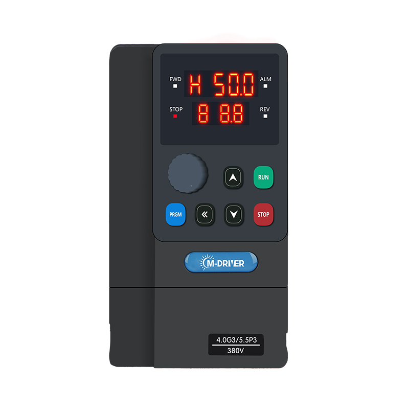
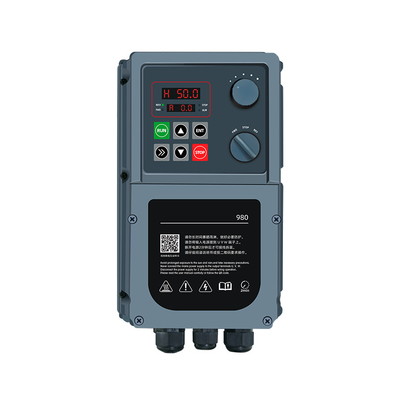
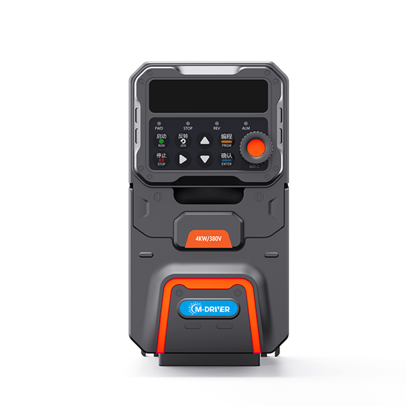
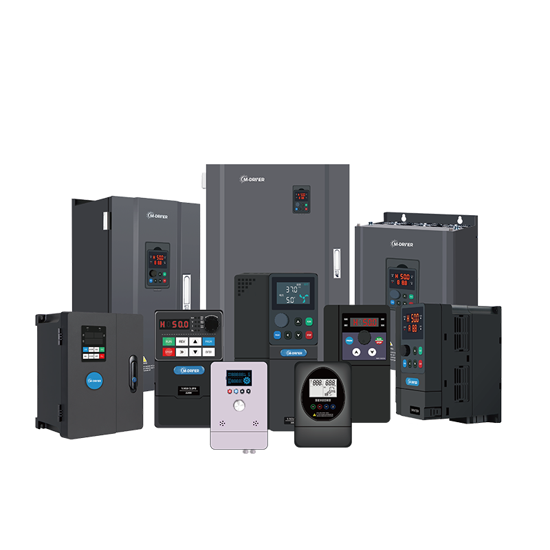
The M-Driver 900 Series Variable Frequency Drive (VFD) is specified for general-purpose industrial applications that include hoisters and cranes. Its open-loop vector and V/F control options, command and frequency interfaces, current/voltage limiting and protection functions provide a practical platform for engineered crane systems. Final suitability still depends on the complete crane design, required safety architecture and verified operating duty.
Start With the Crane Motion, Not the Drive Catalog
“Crane” can mean very different loads. An overhead travelling crane may have separate hoist, trolley and bridge travel motors. A gantry crane adds outdoor exposure. A winch may have a drum and gearbox with high reflected inertia. A compact electric hoist may cycle frequently even though its motor is small.
List every motion that will use a drive:
hoisting and lowering;
trolley travel;
bridge or gantry travel;
slewing or luffing where applicable;
auxiliary grab, magnet or positioning motions.
The hoist axis is normally the most demanding because gravity assists one direction and opposes the other. Travel axes may have lower continuous torque but can still require high breakaway torque, frequent reversing and controlled stopping.
Size by Rated Current and Duty
Record the complete motor nameplate
Provide rated voltage, rated current, power, frequency, speed, connection, insulation class and duty marking. If the motor has an electromagnetic brake, provide its coil voltage and control arrangement separately. A photograph of the complete nameplate reduces transcription errors.
Rated current is the first electrical sizing reference. Two motors with the same kilowatt rating can have different currents and thermal behavior. The selected drive must cover the actual motor current after considering duty, ambient temperature, altitude, cabinet conditions and switching frequency.
Describe the operating cycle
- A hoist rarely runs continuously at one steady point. Record:maximum suspended load and empty-hook load;
- lifting and lowering time per cycle;
- starts, stops and reversals per hour;
- maximum consecutive cycles;
- loaded and unloaded speed range;
- time spent holding, creeping or positioning;
- emergency-stop and limit-switch requirements.
Average current alone can hide a demanding cycle. Repeated acceleration, plug-like reversals, braking and low-speed positioning create electrical and thermal stress. If an existing machine is being retrofitted, a current trace over a representative production cycle is more useful than a single clamp-meter reading.
Treat the Mechanical Brake as a Coordinated Safety Device
The VFD controls motor torque; the mechanical brake holds the load when required. These are related functions, but they are not interchangeable. The control sequence must establish adequate motor torque before brake release and apply the brake only at an appropriate speed and torque condition. Incorrect timing can produce rollback, shock loading, brake wear or a current trip.
Define the brake-release output, brake feedback input, pickup and drop-out delay, low-speed threshold, torque-proving requirement and fault response in the system design. Limit switches, overload devices, emergency stops and other safety functions must follow the applicable crane standards and risk assessment. Do not use a normal run command as the sole safety stop.
Calculate What Happens During Lowering
When a suspended load is lowered, the motor can be driven by the load. Energy then flows back toward the drive DC bus. If the system cannot absorb or return that energy, bus voltage rises and the drive may trip. The required braking solution depends on load, speed, deceleration time, lowering duration and cycle frequency.
Possible architectures include a brake chopper and resistor, a regenerative unit, a common DC system or another engineered energy-handling arrangement. They are not interchangeable, and a resistor selected only by ohms can overheat if its power and duty rating are insufficient.
For an RFQ, provide the suspended mass, drum diameter, reeving ratio, gearbox ratio and efficiency, target lowering speed, deceleration time and cycles per hour. The exact M-Driver 900 Series VFD model determines whether braking hardware is built in, optional or external; confirm the model-specific arrangement before ordering components.
Define the Speed and Torque Envelope
State the minimum controlled speed, normal speed and maximum mechanical speed for each motion. Long low-speed operation can reduce cooling in a shaft-cooled motor. Conversely, operation above base frequency can reduce available motor torque and must stay within the mechanical limits of the motor, brake, gearbox, drum and crane structure.
Open-loop vector control can improve low-speed torque behavior compared with a simple V/F setup, but it does not remove the need for correct motor data or a suitable motor. If the application requires zero-speed load holding, very precise positioning, anti-sway control or closed-loop torque verification, define those needs explicitly. They may require feedback or dedicated crane-control functions outside a general-purpose VFD.
Review Acceleration, Deceleration and Reversing
A short ramp asks for more accelerating torque and current. A fast stop asks the electrical and mechanical system to dissipate more energy in less time. Begin from the required material-handling performance, then verify whether the motor, drive, brake, resistor or regenerative equipment, gearbox and structure can meet it together.
Use S-curves where they help reduce mechanical shock and load swing, but do not assume one ramp fits every motion. The hoist, trolley and bridge can need different acceleration, deceleration and jerk limits. Reversing logic must prevent contradictory commands and respect brake and contactor sequences.
Check Power, Wiring and Installation Conditions
Document supply voltage and frequency, transformer capacity, permissible voltage variation, protective devices and grounding arrangement. State motor cable length, cable type, shielding and routing. Separate control and power wiring, and coordinate EMC measures with the site standard.
For long motor leads, output-side filtering or a reactor may be required. The M-Driver 900 Series VFD installation guidance calls for an AC output reactor near the drive when the motor cable exceeds 100 m and recommends shielded motor cable to reduce interference. Cable capacitance, motor insulation and switching conditions still need project-specific evaluation.
Ambient temperature, altitude, dust, moisture, vibration, corrosive vapor and cabinet cooling affect the usable drive rating. Put the VFD in an enclosure and thermal design appropriate for the real site; do not infer environmental suitability from a catalog image.
A Practical Crane VFD Selection Workflow
Identify every controlled motion and the worst loaded direction.
Capture each motor and brake nameplate.
Record maximum load, speed, gearbox, drum and reeving data.
Describe duty cycle, starts per hour, reversing and low-speed time.
Size from motor current and overload demand, with environmental derating.
Calculate lowering and stopping energy; select the braking architecture.
Define brake sequencing, limits, interlocks and required safety functions.
Confirm cable length, EMC, cabinet cooling and accessories.
Commission unloaded first, then increase load under an approved test plan.
Common Selection Mistakes
Selecting from motor power only
Motor current, duty, overload, brake coordination and lowering energy can all invalidate a simple kW match.
Treating the mechanical brake as an ordinary contactor load
Brake release and application must be coordinated with torque and speed. A generic delay copied from another hoist is not a validated sequence.
Ignoring lowering energy
A drive can accelerate correctly and still trip during lowering or a fast stop. Braking power and duty must be calculated.
Assuming a larger drive solves every problem
Oversizing does not fix an undersized brake, wrong gearbox, unsafe control sequence, weak motor, poor cooling or inadequate resistor.
Quoting without the operating cycle
“Ten starts per hour” and “ten starts in one minute followed by a long pause” are not thermally equivalent. Give the real sequence.
FAQ
Should a crane VFD be sized by kW or current?
Use motor rated current and the required duty as the primary electrical references, then verify overload demand, environmental derating, braking and control requirements. Kilowatts alone are insufficient.
Does every hoist need a braking resistor?
Not necessarily. The energy-handling architecture depends on the mechanical system, load, lowering time, speed, deceleration and frequency of operation. Confirm the exact drive model and calculated braking duty.
Can a VFD hold a suspended load without a mechanical brake?
Do not assume so. Load holding and safety must be defined by the crane risk assessment and applicable standards. A mechanical brake and verified control sequence are commonly required.
What data speeds up a crane VFD quotation?
Send motor and brake nameplates, supply, maximum load, motion speeds, gearbox and drum data, duty cycle, starts and reversals, cable length, environment, braking requirement and the control/safety interface list.
Is open-loop vector control enough for every crane?
No. It can support strong general-purpose motor control, but precise positioning, zero-speed torque verification, anti-sway or advanced safety functions may require feedback or dedicated crane controls.
Send a Complete Motion Profile, Not Just a Motor Power
For an M-Driver crane or hoist VFD selection, send the motor and brake nameplates plus the actual motion cycle. M-Driver can then review current, control mode, braking arrangement, accessories and installation conditions as one system.