
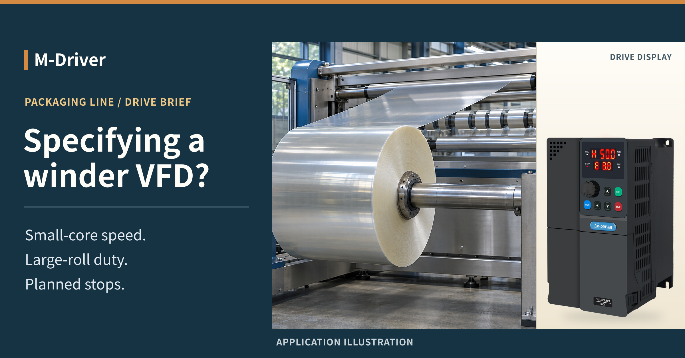
For a center-driven film rewinder, size the drive system for the whole roll, not for the motor nameplate or the empty shaft alone. A small core needs high shaft speed to keep up with the web. A larger roll turns more slowly at the same line speed but requires more shaft torque for the same web tension. A loaded stop adds a separate braking question. This winder VFD selection guide shows packaging equipment builders what to put in a quotation and what to prove before accepting the machine.
Translate the Roll Range Into Motor Duty
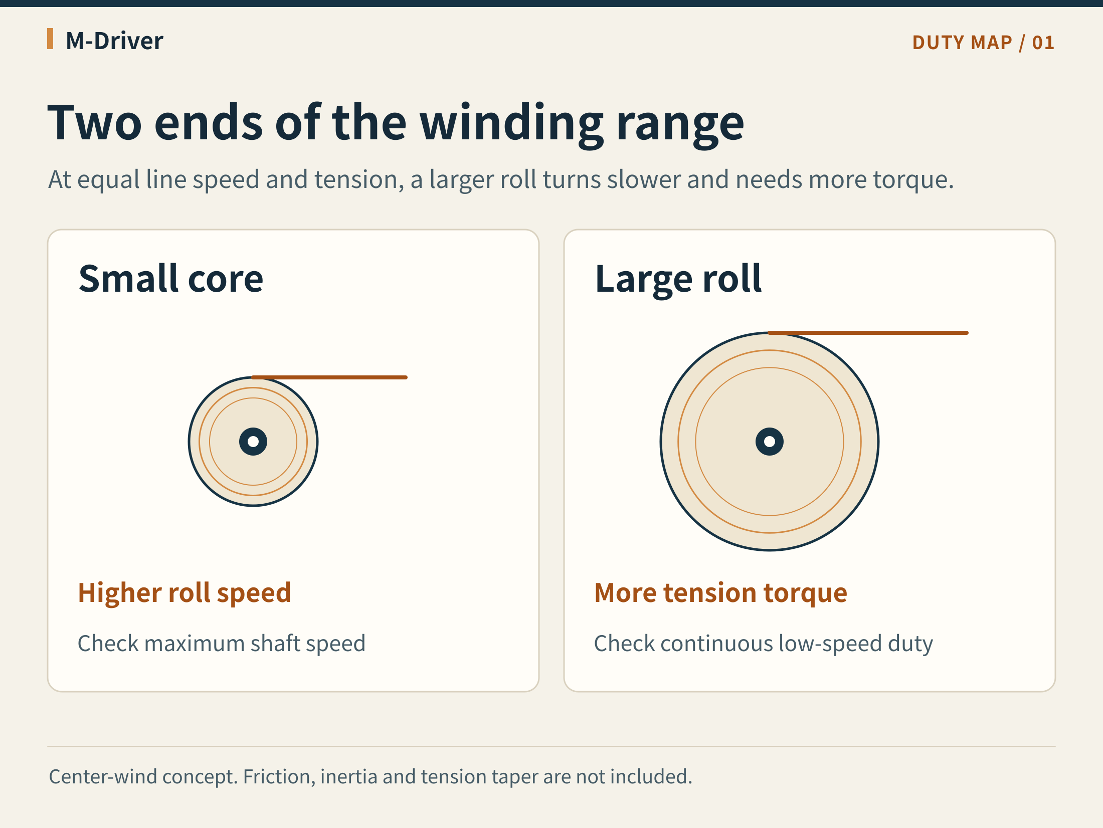
Begin with the smallest core, largest finished roll and usable line-speed range for each material recipe. A center-driven shaft must change speed as diameter changes. At a fixed line speed, a roll three times the core diameter turns at one-third of the core speed. For the same web tension, its tension-related shaft torque is three times that at the core. Those ratios describe the web contribution only; they exclude inertia, friction and transmission losses. If the recipe reduces tension as diameter increases, use the specified tension at each diameter rather than assuming the largest roll always needs the highest torque.
Convert roll shaft speed and torque to the motor side using the actual gearbox or belt ratio and the relevant losses. Paying for a larger drive does not increase a gearbox's mechanical speed limit or restore motor torque lost above its base speed. Check the motor and transmission limits at the fastest recipe on the smallest core. Then check current, motor cooling and the ability to maintain usable torque at the slowest sustained production point. A large roll at normal speed may be easy to run, while threading or a slow recipe at a large diameter can be a harder thermal case.
Define Winding Tension Control Before Choosing the Drive
Specify what generates the reference and what corrects it. A line shaft encoder or upstream controller can supply the line-speed reference. The winding controller then needs a usable diameter value or estimate. A wrong core diameter is not merely a display error: it changes the calculated roll speed and can upset the web when the machine starts. Define where the diameter is initialized at roll change and what happens if its feedback is invalid.
In a speed-based arrangement, the system derives a roll-speed reference and adjusts it to control tension or dancer position. A load cell measures a force signal that must be interpreted with the roller geometry and calibration. A dancer measures position, which the controller holds within the available travel while the dancer mechanism establishes web tension. In a torque-based arrangement, the controller estimates or measures diameter to set torque and the design must enforce a suitable speed limit if the web is absent. Neither method automatically fits every material, spool or machine layout.
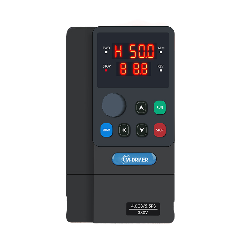
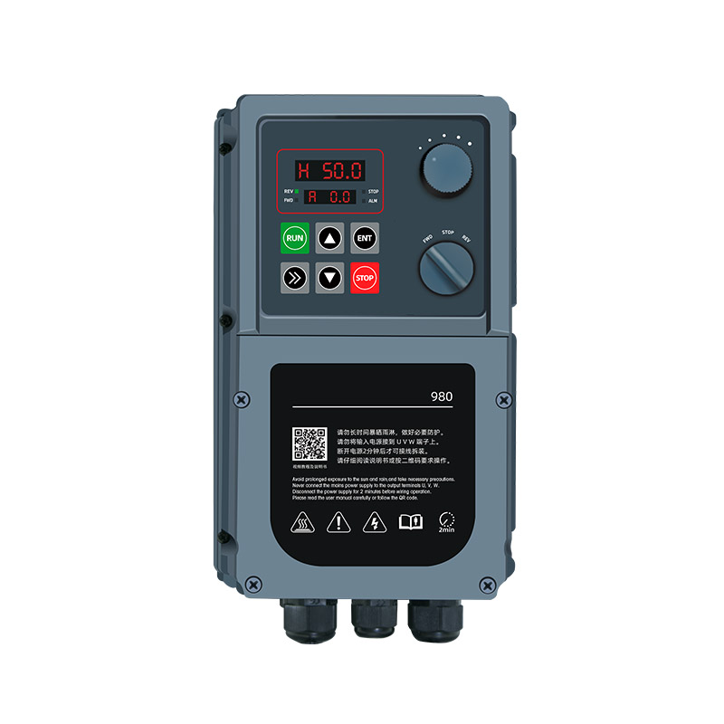
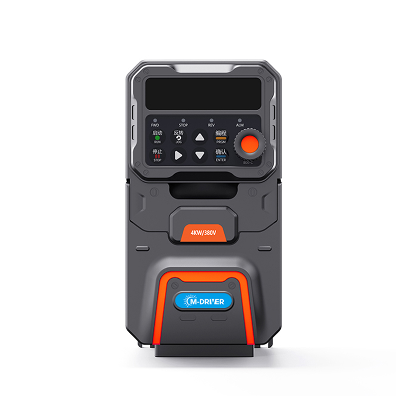
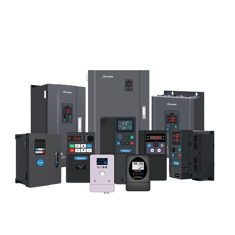
The M-Driver 900 Series General-Purpose Vector Variable Frequency Drive (VFD) supports open-loop vector and V/F control. That makes the available control mode one item to review against the motor and the proposed architecture. It is not a claim that this series provides a dedicated winder controller, roll-diameter calculation or a guaranteed tension tolerance. Compare the project requirements with the M-Driver industrial AC drive range before assigning the tension loop, feedback interfaces and command responsibilities.
Separate Running Torque From Acceleration and Braking
Ask for the full roll mass or the inertia estimate at the shaft, the acceleration profile and the planned stop profile. The pull required to maintain tension is only one part of the load. A full roll can add significant rotational inertia, while an aggressive line ramp can demand extra torque even before the roll grows large. A production line that changes recipes and stops several times an hour has different braking duty from one that stays at speed all shift.
Specify whether any unwind axis is motor-driven and expected to generate during normal tension control. That is a different requirement from a brief regenerative event when a rewinder decelerates. In a stop that regenerates into the drive's DC link, the project needs a way to handle the returned energy. A drive, resistor-based braking system or regenerative solution must be evaluated for the actual peak and repeated duty and its installation conditions. Do not assume an accessory that passes a single stop can support a repeated-stop cycle. Confirm which items the quote includes and who is responsible for checking them.
Normal process stopping, loss-of-web response and machine safety functions need their own design review. The fastest production stop should not be used as a substitute for a safety specification. Agree what the machine is allowed to do on a web break, a change of mode or a loss of feedback; do not discover the behavior during a loaded acceptance test.
Send a Winder VFD RFQ That Suppliers Can Compare
Start the inquiry with an operating envelope rather than one nominal speed and one motor kW. Include the condition that produces each extreme; maximum speed and maximum tension do not necessarily occur in the same recipe. If you lack a number, mark it as an assumption to be validated and name who will supply it.
| What to send | What to ask the supplier to check |
|---|---|
| Winder type, shaft arrangement and supported materials | Whether the model assumes center winding, and which shaft is being driven |
| Core and full-roll diameters, material width, line speed and recipe tension | Shaft speed at the core, tension torque across the diameter range and any tension taper |
| Motor nameplate, feedback, gear ratio and speed limits | Continuous duty at the low-speed end, allowable motor speed and usable torque at the high-speed end |
| Roll mass or inertia, ramp profile and frequency of stops | Transient current, braking energy path and repeated-stop duty |
| Existing controller, tension feedback, cabinet environment and supply | Interface ownership, environmental limits and scope of supply |
| Sample material and acceptance limits | Who will validate line speed, tension, stop behavior and temperatures under load |
Ask every bidder to state the assumed operating points, the motor and drive responsibilities, and any excluded components. This exposes the difference between a drive-only price and a package that can be integrated and accepted. A short agreed list is more useful than a longer list of features that never gets tied back to a material recipe.
Prove Three Operating States Before Acceptance
First, prove the small-core ramp with the machine's agreed material and speed profile. Record line speed, roll speed and the tension peak, not just whether the drive finished the ramp. Next, hold a large-roll production point long enough for the agreed comparison of tension, current and temperature. Watch whether the run is being sustained within the motor and drive limits rather than relying on an overload allowance for normal production.
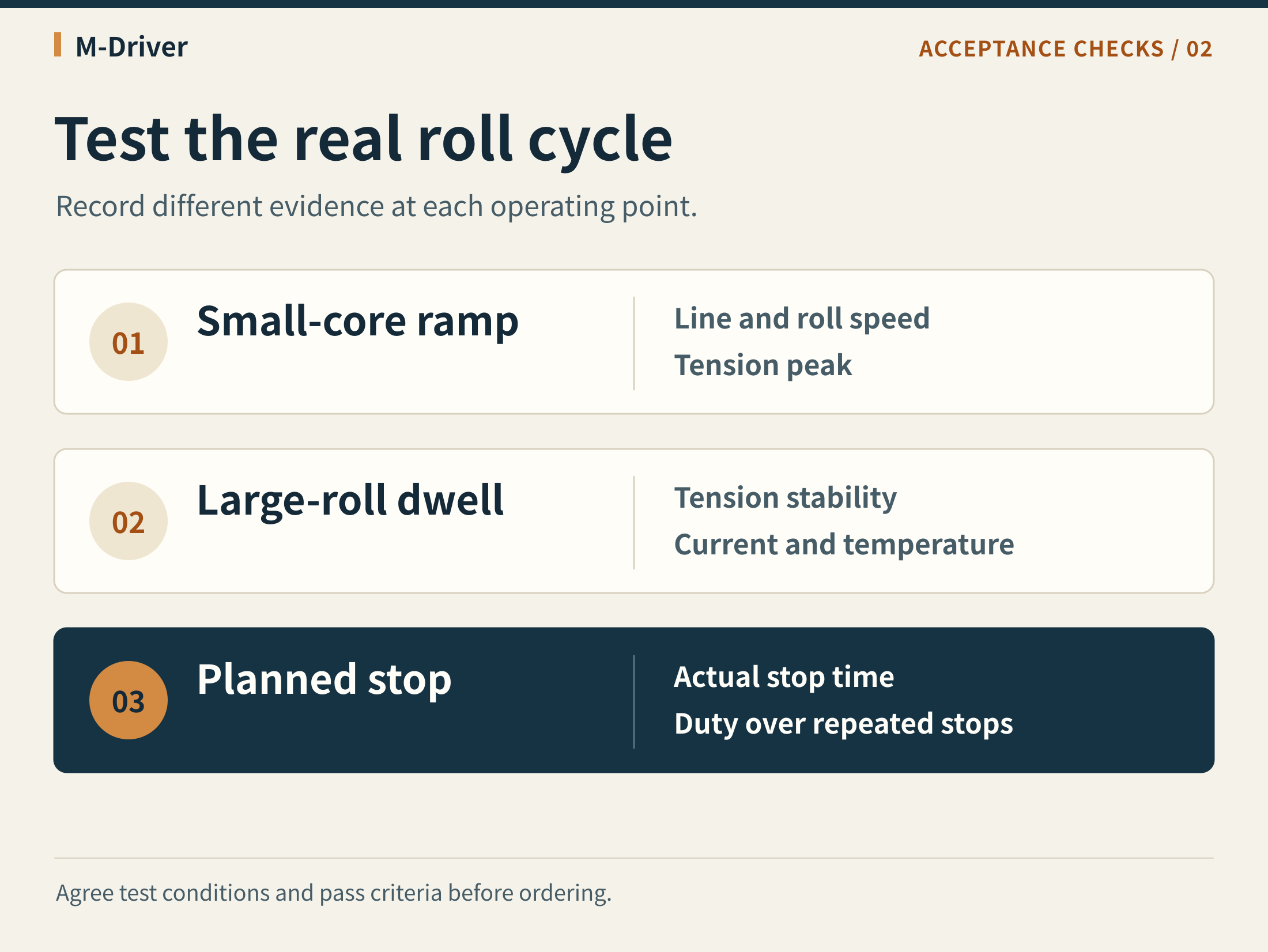
Finally, verify the planned loaded stop and its repeated duty under the approved test plan. Record stop time, relevant drive and brake status, and any warnings. A single empty-run stop does not reproduce a loaded roll's energy. Set pass limits and measurement points before the test, and leave electrical checks and machine movement to authorized personnel following the site's procedures.
Frequently Asked Questions
Can I size a rewinder drive from motor kW alone?
No. Motor kW does not define shaft speed at the core, sustained low-speed current, the torque needed for the web or the duty of repeated stops. Use the roll and speed ranges, the motor and transmission data, and the expected operating cycle together.
Does a larger roll always need higher tension torque?
Only when comparing equal web tension and the same center-drive geometry. A taper-tension recipe changes the force as the roll builds. Friction and acceleration can also move the peak torque away from the largest roll.
Can a drive's process PID replace a winding controller?
Not by default. A PID loop alone does not define how to calculate diameter, limit speed on a missing web, coordinate line ramps or handle roll changes. Decide which device owns these functions and check the required response and interfaces.
What is the first thing to include in a winder VFD quotation request?
Send the minimum and maximum roll diameters, the line-speed range and the tension requirements for each material. Add the motor and gearbox data and the planned braking cycle so the supplier can compare the speed and torque extremes separately.
Discuss Your Rewinder With M-Driver
Send your roll dimensions, speed range, tension recipe and motor nameplate to M-Driver for a drive selection review. If the machine includes motor-driven unwinding or repeated loaded stops, attach the stop profile and the proposed braking arrangement so those cases can be reviewed separately.