
A successful first startup begins before the RUN command is pressed. The most useful VFD commissioning checklist is not a list of random parameters; it is a controlled sequence that verifies the drive, supply, motor, wiring, command path and mechanical load before energy is applied.
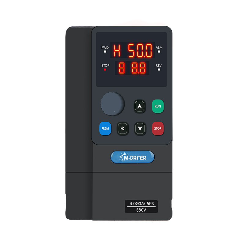
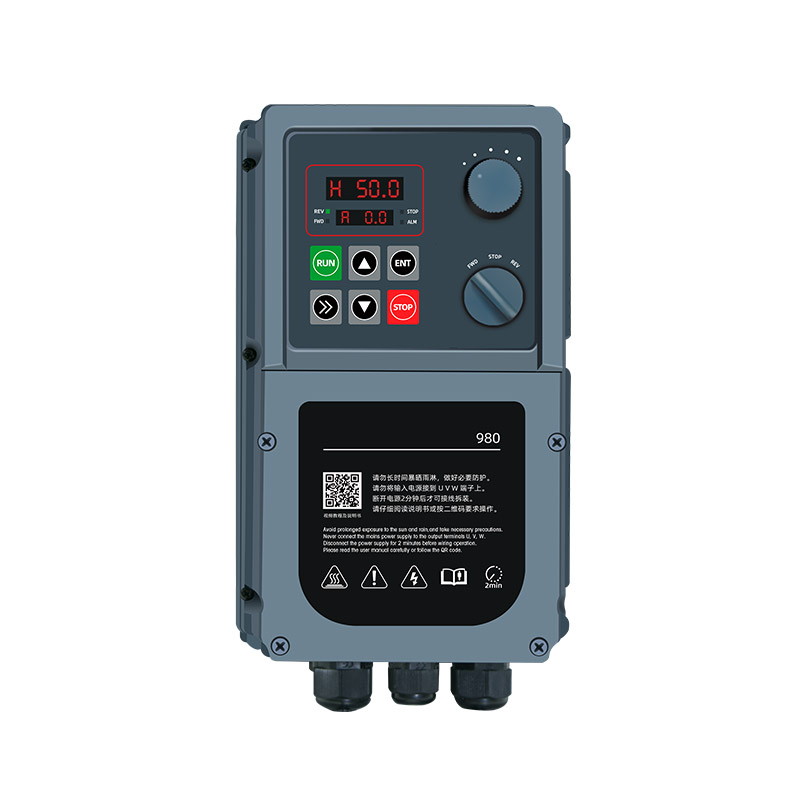
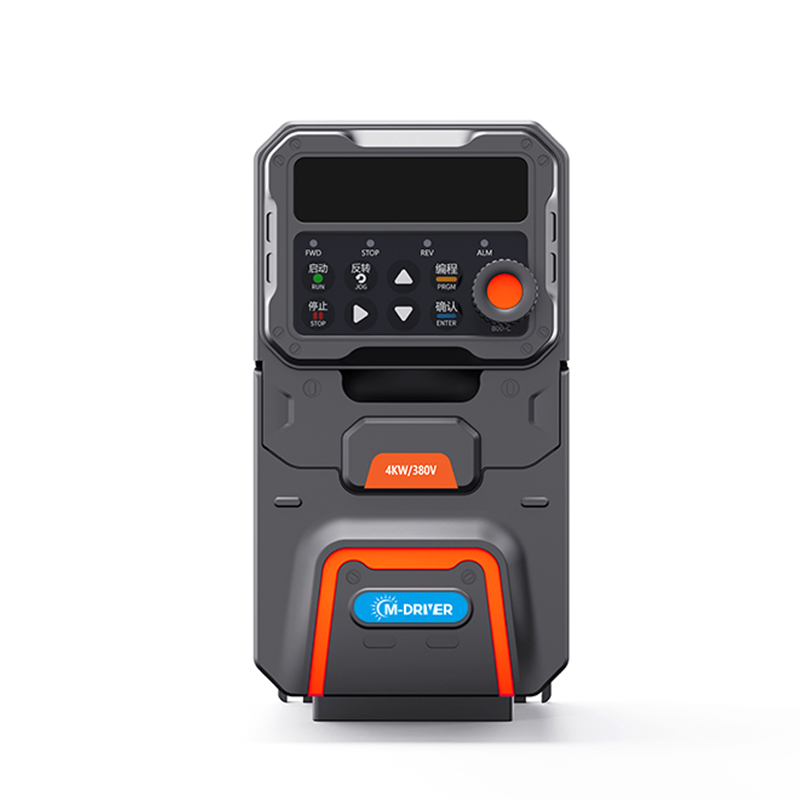
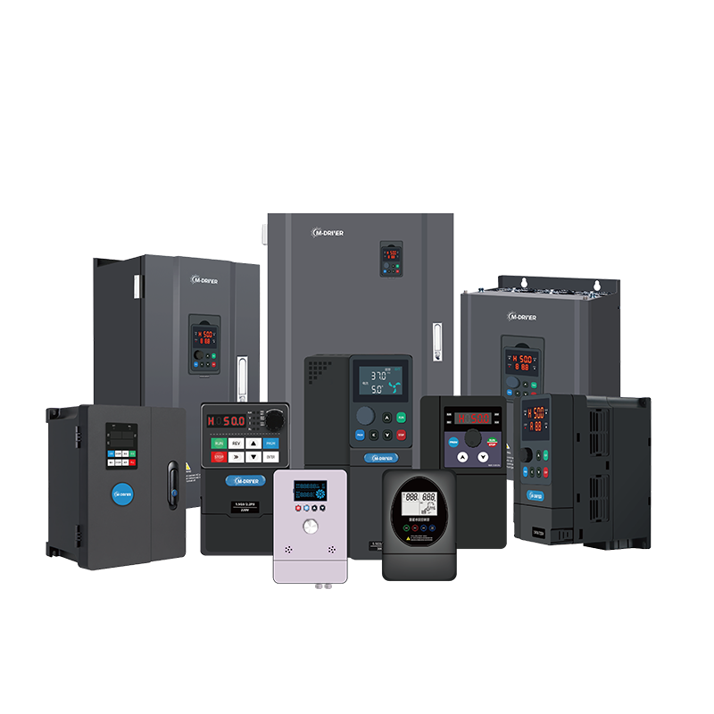
This guide provides a practical workflow for technicians, panel builders and machine integrators. It can be used with the M-Driver 900 Series Variable Frequency Drive (VFD) as a project checklist, while the exact ratings, terminals and settings must always match the selected model and motor.
Why VFD Commissioning Needs a Defined Sequence
Many startup problems appear to be drive faults but originate elsewhere: a supply that does not match the drive rating, a motor connected incorrectly, incomplete grounding, the wrong command source, an open safety circuit, reversed motor direction or motor data copied from another machine.
A defined VFD commissioning procedure makes each decision traceable. It also prevents a technician from changing several parameters at once and losing the ability to identify the real cause of a problem.
The objective is simple: prove one part of the system at a time, beginning with the installation and ending with a controlled loaded test.
Step 1: Confirm the Drive and Application Match
Before installation or energization, compare the project documents, drive nameplate, motor nameplate and incoming supply.
Verify:
input voltage, frequency and phase;
drive output current rating and duty classification;
motor rated voltage, current, frequency, speed and power;
required speed range and direction;
whether the load starts empty or already loaded;
acceleration, deceleration and braking requirements;
enclosure, temperature, altitude, contamination and ventilation conditions;
required command, feedback, communication and safety signals.
Do not select or approve a drive only because its power number matches the motor power. Motor rated current and the application duty are essential checks. If the project has high starting torque, frequent starts, rapid deceleration or a regenerative load, those conditions must be evaluated before the first start.
Step 2: Make the Installation Safe to Inspect
Use the site’s lockout and tagout procedure. Isolate all energy sources, wait for the required DC-bus discharge time and verify the absence of dangerous voltage with suitable equipment. Only qualified personnel should open the panel or work on power terminals.
Inspect the drive before touching its wiring. Do not energize equipment with visible damage, missing parts, water ingress or conductive debris. A drive designed for installation inside a protected cabinet needs sufficient cooling clearance and protection from drilling dust, metal particles, moisture and corrosive contamination.
Confirm that the protective earth conductor is correctly installed. Grounding is a safety requirement, not an optional method for reducing electrical noise.
Step 3: Verify Power and Motor Wiring
Trace every power conductor against the approved schematic. The incoming supply must be connected only to the designated input terminals. Never connect the mains supply to the VFD motor-output terminals.
Check the motor leads, protective earth and terminal torque. Look for loose strands, damaged insulation, unapproved splices and conductors that could contact the enclosure. If an external braking resistor is used, confirm that it is connected to the specified braking terminals—not directly across the DC bus—and that its resistance, power rating and installation meet the project design.
Route control wiring away from power wiring. Where the two must cross, a right-angle crossing helps reduce interference. For the M-Driver 900 Series, keeping control and power cables physically separated is an important installation practice.
Step 4: Test the Motor and Cable Correctly
Insulation testing requires a strict boundary between the motor circuit and the drive. Disconnect the motor and its cable from the VFD before using an insulation resistance tester. Never apply a megohmmeter or high-voltage insulation test to the drive’s power or control terminals.
After the motor and cable pass their independent checks, verify continuity and phase-to-phase consistency before reconnecting them. Confirm that the motor is mechanically secure and that personnel are clear of shafts, couplings, belts, fans and other moving parts.
Step 5: Enter Verified Motor Data
Use the actual motor nameplate. Do not reuse motor data from another drive merely because the motors appear similar.
Enter or verify the rated motor voltage, current, frequency, speed and power required by the control mode. Then select the command source and frequency reference that the machine will use: keypad, terminals or communication. Confirm minimum and maximum frequency limits before running.
If motor identification or autotuning is required, determine whether the selected routine can rotate the motor. Decouple or secure the machine as necessary and keep the work area clear. An autotune should only be performed under conditions permitted by the machine and process.
Step 6: Prove Commands, Interlocks and Protection
Before commanding motion, verify the logic path.
Check:
emergency stop and safety chain status;
run permissives and external interlocks;
local/remote selection;
forward/reverse authorization;
analog reference polarity and scale;
digital input functions;
relay or transistor output logic;
communication address and command ownership;
motor thermal and current protection settings.
A common startup delay occurs when the drive is healthy but is listening to the wrong command source. Another occurs when a terminal function has been assigned differently from the electrical drawing. Confirm the status on the keypad or monitoring screen before changing parameters.
Step 7: Perform a Low-Speed Direction Test
The safest VFD first start is a short, controlled direction test at a low reference. If possible, begin with the machine unloaded or mechanically decoupled.
Use jog or a low frequency command and observe the shaft direction. Stop immediately if the direction is wrong, if the motor does not accelerate smoothly, or if there is abnormal noise, vibration or current. Correct direction only after isolating the system and following the approved wiring or command-logic method. Do not change motor leads on an energized circuit.
At this stage, also verify that the displayed frequency, command source and operating status agree with the actual command.
Step 8: Run an Unloaded Test
Increase speed gradually within the approved test range. Observe:
output frequency and motor speed;
output current on each operating point;
DC-bus or supply stability when available;
motor sound, vibration and temperature;
mechanical alignment and airflow or lubrication;
response to stop commands and normal deceleration.
The current should make sense for an unloaded machine. An unexpected increase can indicate mechanical binding, a motor connection problem, incorrect motor data or an unsuitable control setup. Do not hide an abnormal condition by simply increasing current limits.
Step 9: Complete a Controlled Loaded Test
Introduce load progressively. Test the real operating range, including the lowest continuous speed, normal production speed and any permitted high-demand condition. Confirm that acceleration time is long enough to avoid unnecessary current stress yet short enough for the process. Confirm that deceleration does not create overvoltage or uncontrolled stopping.
For a cyclic machine, one successful start is not sufficient. Observe several cycles and include the worst credible normal load. Verify interlocks, fault response, restart behavior and process feedback under controlled conditions.
Step 10: Record the Commissioning Baseline
Good variable frequency drive commissioning ends with a record that can be used later for maintenance and troubleshooting.
Record:
drive model and rating;
motor nameplate data;
final command and reference sources;
control mode and main limits;
acceleration and deceleration times;
current at key speeds and loads;
direction and interlock test results;
final parameter backup or export;
open issues and responsible person.
This baseline is more valuable than a photograph of the keypad alone. It shows what “normal” looked like when the machine was accepted.
Common First-Startup Mistakes
Changing many parameters at once
Make one controlled change, record it and retest. Bulk changes make fault isolation difficult.
Copying motor data from another machine
Similar-looking motors can have different rated current, speed or connection requirements. Use the actual nameplate.
Testing insulation through the drive
High test voltage can damage electronic components. Separate the motor and cable from the VFD first.
Skipping the direction test
Incorrect rotation can damage pumps, fans, conveyors or mechanical processes. Prove direction at low speed before loading.
Treating a fault reset as a repair
A reset clears a state; it does not correct the cause. Capture the fault, operating current and conditions before making changes.
Using the M-Driver 900 Series in a Commissioning Plan
The 900 Series supports V/F and sensorless vector control, keypad, terminal or communication commands, analog references, built-in PID and Modbus communication. These options help it fit different machine-control architectures, but they also make command ownership and parameter verification important during startup.
Choose only the functions required by the machine, document the selected control path and prove the basic motor operation before enabling more complex process logic.
FAQ
What should be checked before starting a VFD?
Confirm supply and drive ratings, motor data, grounding, input/output wiring, control source, frequency limits, interlocks, mechanical readiness and a safe low-speed test plan.
Should a motor be connected during VFD autotuning?
Yes, but the exact mechanical condition depends on the tuning method. Some routines can rotate the motor. Follow the selected drive’s procedure, secure the machine and keep personnel clear.
Can I megger a motor while it is connected to the VFD?
No. Disconnect the motor and cable from the drive before insulation testing. Never apply the test voltage to VFD power or control terminals.
Why does the motor not run even when the VFD shows no fault?
Check command ownership, run permissives, local/remote status, digital input assignments, frequency reference and safety interlocks before changing motor parameters.
What data should be saved after commissioning?
Save the final parameter set, motor nameplate data, current at representative loads, acceleration/deceleration times, control sources, direction, interlock results and any exceptions.
Build a Repeatable First-Startup Process
A disciplined VFD startup checklist reduces avoidable risk and shortens troubleshooting. If you are planning a machine or panel around the M-Driver 900 Series, send M-Driver the motor nameplate, supply details, load type, speed range, duty cycle, control method and braking requirement. The engineering team can help confirm the drive configuration before commissioning begins.